Goal
Demonstrating how residential adversary traffic can be simulated in an ethical method using your own infrastructure
Audience
Red Team
Blue Team
Security Researchers
IoC
Multiple employees using the same (unknown) IP address
Employees logging in via uncommon networks (by ASN)
Employees logging in via a new mobile provider (by ASN)
Disclaimer
This article is written for educational purposes and is intended only for legal penetration testing and red teaming activities, where explicit permission has been granted. If you wish to test any of the scripts provided, refer to the disclaimer.
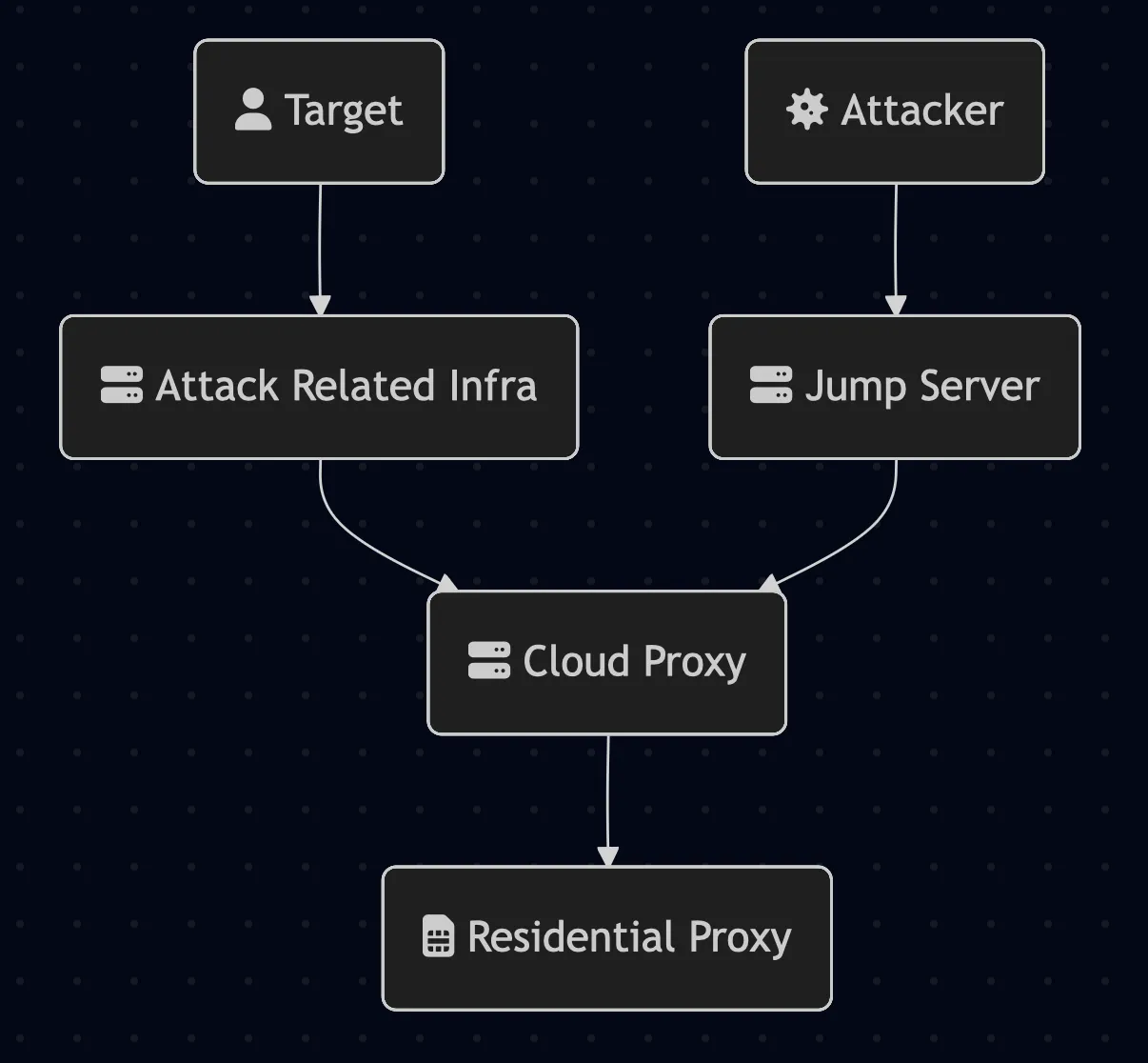
During security research and assessments, we are often juggling VPN connections or routing our traffic through our own cloud servers. Adversaries do not face this challenge. They often use residential proxies to mask their traffic, blending in with benign and real traffic. From an ethical perspective, we do not want to make use of these kinds of services. Why? We will get back to that in a moment. First, let’s take a look at a simplified adversary infrastructure making use of a residential proxy:
Simplified design of a residential proxy
To work around this, we set out to research creating our own residential proxy as an alternative. This research walks through setting up a residential proxy using an anonymous SIM card, a Raspberry Pi 3, an LTE modem, and Ubuntu Server. The end result uses a WireGuard tunnel that routes cloud traffic through a mobile network, providing a residential IP address for your infrastructure.
Since adversaries already use these techniques, simulating them is essential for understanding real-world threats and strengthening defensive capabilities. As always, this research should only be applied to infrastructure you own or for which you have explicit written authorization to test.
Why Are We Doing This?
Some residential proxy providers distribute SDKs to apps, particularly “free money” reward applications, to monetize user bandwidth without meaningful disclosure. Users install these apps expecting passive income, but developers silently integrate proxy functionality through deceptive terms of service and server-side monetization that requires no visible opt-in. Beyond consensual models, malicious operators deploy botnets to compromise millions of devices without user knowledge, reselling bandwidth for fraud, account takeovers, bot automation, and ransomware infrastructure.
Even legitimate providers operate in a legal gray zone where buried consent language may not constitute informed disclosure, leaving unwitting device owners liable for proxy traffic originating from their IPs.
An important part of our research is that while we simulate attackers, we want to do so in an ethical manner. If we were to make use of one of these unethical or even illegal residential proxies without knowing where our traffic is routed through, we would actively support the parties behind it. Obviously, we don’t want to do that.
So, because we’re avoiding this, what are our options?
Run assessments and research from a company-owned infrastructure.
Run assessments and research from a full cloud infrastructure.
Run assessments and research from a self-hosted infrastructure.
Or, how about this: we build our own residential proxy! No ethical considerations needed, only (many evenings of) tinkering and tweaking. Just the way we like it.
Note: we’re researching proxying cloud-based network traffic through an anonymous SIM card. The SIM card can be purchased anonymously, but there are other identifiers which we didn’t touch, for example, the IMEI linked to the LTE dongle. These are known to be spoofable, but this was not the goal of our research.
Components
Before we start, we need to get our hands on some hardware. So first things first, we opened up a few drawers and looked at wat was already available. The first attempts were futile, a few old routers seemed promising, but alas, they had no USB ports. Buying a new SIM-router could also be an option, but we wanted a level of control so we could actually make it into a proxy! After some light reading, we decided either OpenWrt or Ubuntu Server would be the way to go, and luckily, a compatible Raspberry Pi 3 was gathering dust in the back of a drawer.
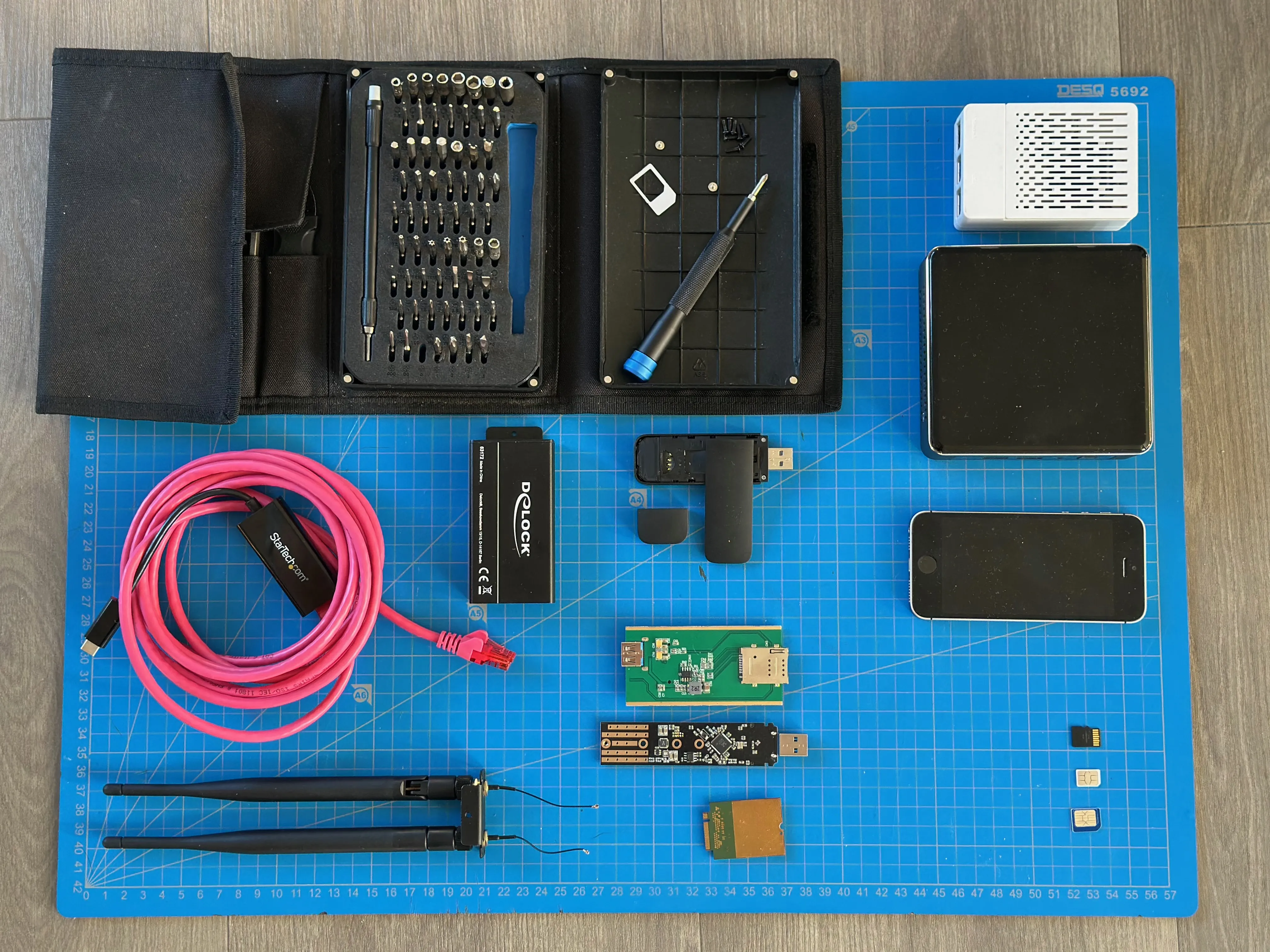
So, skipping to the end, the following hardware was used. And no, this is probably not the most cost efficient set-up. But, already having a spare Raspberry Pi, this was the way.
Item
Purpose
Cost
Raspberry Pi 3B v1.2 + case/fan
Runs Ubuntu server
~€100
Micro SD card 64 GB
Houses
~€10
Alcatel IK41VE1
LTE USB dongle
~€60
Anonymous data SIM
Provides residential IP
~€15
However, this is not all the equipment that was used. Our first experiment failed (horribly). Many hours were spent in picocom getting the DeLock/DELL combination to work with OpenWrt on the Raspberry Pi, but eventually we lost hope of ever getting this to work. In short, the modem didn’t seem to get enough power from the raspberry and almost everyAT-debug command we threw at it was denied. Because of the power issues (and struggling with the Pi’s performance), an Intel NUC was used to verify everything works before switching back to the raspberry.
Item
Purpose
Cost
Intel NUC7i5BNK
Way more powerful (stable and fast testing)
-
Dell DW5811e (3P10Y) M.2 LTE
Modem (Sierra EM7455 chipset)
~€50
USB 3.0 Converter voor M.2 Key B module with SIM slot and casing
Houses modem + SIM slot
~€60
It got a bit out of hand
After we’ve created a working setup script for the Alcatel/NUC combination, we converted the script for the Raspberry Pi 3, seeing this is a different architecture.
Hardware
In regards to operational security, we need a new SIM card. As mentioned, many evenings were spent tinkering with the initial hardware without ever achieving an LTE connection. Sanity was lost, we knew this had to work. So, the SIM card was plugged into a mobile phone to verify it actually works. Of course, now we do, so with a new SIM card this shouldn’t happen anymore.
Having said that, preparing the Alcatel dongle wasn’t that big of a deal. Just open the modem enclosure and locate the SIM card holder. Insert your anonymous data SIM card into the SIM slot, the orientation should be marked on the enclosure.
In regards to the Raspberry Pi, flash the latest Ubuntu Server LTS for Raspberry Pi on your SD card and plug it in. Note that a working internet connection is needed to install the required packages before setting up the modem.
Configuring the LTE Modem
This is where the fun started, so much “fun”. In the end most issues were automated through troubleshooting and suffering, but the following issues still haunt us:
Timing is everything. The USB dongle and ModemManager do a little dance after connecting, which takes between 5 and 60 seconds.
USB modes. Are you a modem? No, you’re an USB drive. Wait, dongle again.
States, settings and profiles.
A new IP on every connection.
Sounds like a blast right? But, considering the time (and money) invested, we wanted to see this work, how hard could it be? After a lot of debugging and finally getting it to work, a feeling of (developer) nostalgia kicked it. That’s all? Yeah, all of our troubles and challenges were filtered down to a relatively short and simple script.
A quick step-by-step of what it does:
Remove the old wwan network config and restart systemd-networkd.
Install modem-manager if needed.
Loop 1: Recognizing the USB dongle and verifying the USB mode.
Loop 2: Connecting LTE, setting up the wwan network and restarting systemd-networkd.
Testing the outbound IP address.
The script is about a 100 lines, so a bit too long to add in this article. You can find all scripts related to this article on in our BYOP repository.
The script consists of two main loops, which can use some context:
Loop 1
This part took quite some time to debug. As described above, we had to deal with USB modes and timing issues. After a while, something became clear: if we couldn’t update the allowed modes (e.g. 4G) to the modem, a physical replug was needed:
The script accounts for that by polling for the connection state and retrying to set the mode. We’re still experimenting with a code-based mode switch or reset of the USB device, but were not able to find a reliable fix (yet). So for now, if the device hangs in this mode, replugging the USB was the quickest fix. So if you were to test the script and would see the following warning, time to get physical:
# We don't want this:error:couldn't set current modes:'GDBus.Error:org.freedesktop.ModemManager1.Error.Core.Unsupported:Unsupported:Settingallowedmodesnotsupported'# We want this:successfully set current modes in the modem
Loop 2
Our modem had some great visual indicators what was happening:
Purple blinking: device is connecting.
Red blinking: the connection failed.
Blue blinking: not connected, maybe trying to connect.
Solid blue: welcome to the internet.
Keeping that in mind, our script has the following visual workflow:
Purple blinking > Blue blinking > Blue solid > Red blinking > Blue blinking > Blue solid.
The first connection always fails. No clue why, but to be frank, we don’t care (anymore). The next connection attempt (after a time-out) does, and that’s what matters. When it does, all we need to do is extract the assigned information like our IP address, prefix and gateway. Using this information, we can set up a network profile and the interface.
# Extract the bearer pathBEARER_PATH=$(sudo mmcli -m"$MODEM" | grep-oE'/org/freedesktop/ModemManager1/Bearer/[0-9]+'||true)# Failed? Skip[[-n"$BEARER_PATH"]]||{sleep 10;continue;}# Extract the bearer infoBEARER_INFO=$(sudo gdbus call --system--dest org.freedesktop.ModemManager1 \--object-path"$BEARER_PATH"\--method org.freedesktop.DBus.Properties.GetAll \
org.freedesktop.ModemManager1.Bearer ||true)# Extract the required information to set up a network profileADDR=$(echo"$BEARER_INFO" | grep-oE"'address': <'[^']*'" | cut-d"'"-f4||true)PREFIX=$(echo"$BEARER_INFO" | grep-oE"'prefix': <uint32 [0-9]*" | awk'{print $3}'||true)GW=$(echo"$BEARER_INFO" | grep-oE"'gateway': <'[^']*'" | cut-d"'"-f4||true)DNS1=$(echo"$BEARER_INFO" | grep-oE"'dns1': <'[^']*'" | cut-d"'"-f4||true)DNS2=$(echo"$BEARER_INFO" | grep-oE"'dns2': <'[^']*'" | cut-d"'"-f4||true)
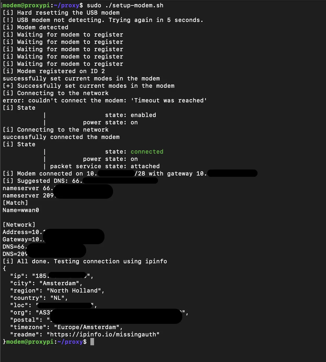
So, lets take a look at the setup script doing its magic:
Look at us being all residential
Tunnel Away
Our next goal is to create a secure WireGuard tunnel between the the Raspberry Pi cloud server, so all traffic from the cloud server can be routed through the Raspberry Pi’s LTE connection without exposing any (new) ports on the Pi. Also, this direction is the only possible way, the LTE is hiding behind NAT.
First things first, lets start with the things that could’ve gone slightly better:
Routes and SSH
Wait, it works? Aaaand its gone. Routing all traffic through WireGuard means ALL traffic, so my SSH route also died. Have fun trying to connect to your cloud server afterwards. The below one-liner adds the currently connected SSH client via the current gateway. Lesson learned, this is the first step.
sudo ip route add $(echo$SSH_CLIENT | awk'{print $1}')/32 via $(ip route | awk'/default/ {print $3}')
Firewall
Everything was set up. Everything was supposed to work. It didn’t.
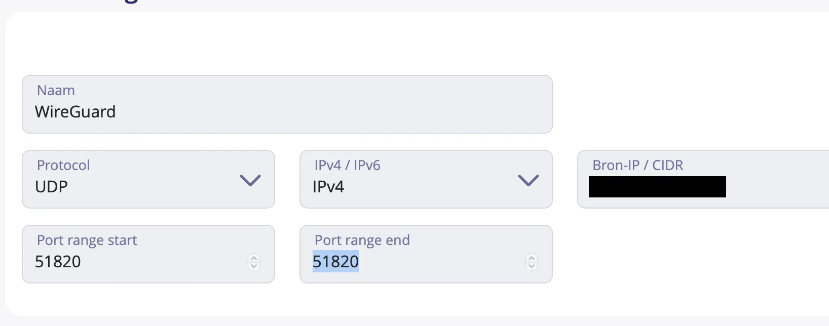
Yeah, don’t forget to check if your WireGuard port (e.g. inbound UDP 51820) is allowed at your cloud provider. We were smart enough to test connectivity with nc, but this is not good enough. Check your settings.
Not that hard, but vital
So without further ado, lets walk through the steps. Keep the following in mind:
Both the Pi and cloud server generate a key-pair. They need each others public keys, so the scripts ask for them.
The order is important. WireGuard must be configured and running before the Pi tries to connect. If it fails for some reason, stop WireGuard on the Pi, restart it on the cloud and start it back up on the Pi. Believe me, we have done this a few times.
Step 1 - Raspberry Pi
The first step in setting up our tunnel is configuring the Raspberry Pi, which is going to be connecting to the cloud server later on in the process. Before you do anything, make sure the LTE connection is connected and exposed on wwan0. In short, the following should be done:
Install the required packages.
Set up a key pair for WireGuard.
Set up a restrictive firewall.
Reload and print information for step 2.
sudo apt update
sudo apt install wireguard wireguard-tools ufw
# Generate the key pairsudo sh -c'umask 077; wg genkey | tee /etc/wireguard/pi_private.key | wg pubkey > /etc/wireguard/pi_public.key'PI_PUBLIC_KEY="$(sudo cat /etc/wireguard/pi_public.key)"# Set up the firewallsudo ufw default deny incoming
sudo ufw default allow outgoing
# SSH access from LAN + WireGuardsudo ufw allow from 10.0.0.0/24 to any port 22 proto tcp
sudo ufw allow from 10.0.100.0/24 to any port 22 proto tcp
# Forwarding between wg0 and LTE (wwan0)sudo ufw route allow in on wg0 out on wwan0
sudo ufw route allow in on wwan0 out on wg0
# Enable IP forwarding in /etc/default/ufwsudo sed-i's/^DEFAULT_FORWARD_POLICY=.*/DEFAULT_FORWARD_POLICY="ACCEPT"/' /etc/default/ufw
sudo ufw enable
sudo ufw reload
sudo ufw status verbose
echo"[+] Peer public key - $PI_PUBLIC_KEY"echo"[i] Now set up the cloud peer"
Step 2 - Cloud Server
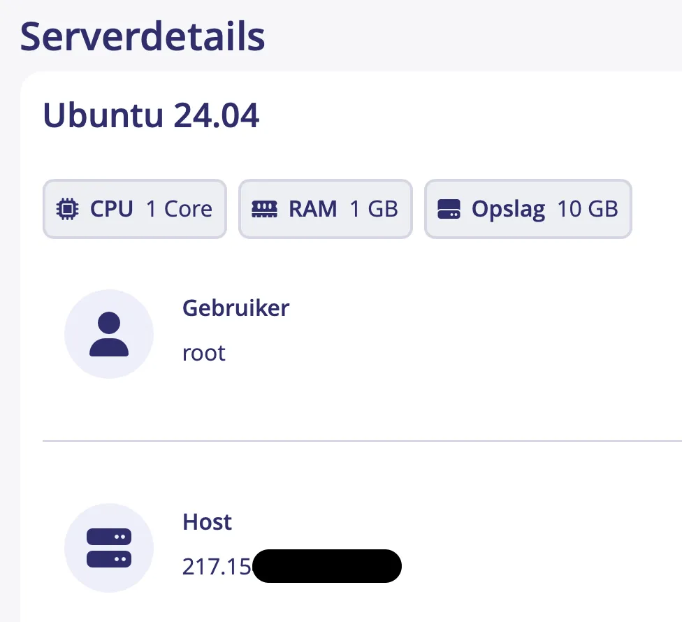
To verify the proof of concept, we got a cheap, out of the box, cloud server running Ubuntu 24.04. As you can see, nothing special:
Nothing special
We refrained from installing any noteworthy tooling on this host, as we expected at least a few wipes would be needed. We were right!
The second step sets up WireGuard on the cloud server, by doing the following:
Important: Allow the current SSH connection by adding a default route. Of course, this is IP-based and prone to changes.
Install the required packages.
Generate (and prompt for) the WireGuard keys.
Create the WireGuard configuration.
Print information for step 3.
Start WireGuard.
sudo ip route add $(echo$SSH_CLIENT | awk'{print $1}')/32 via $(ip route | awk'/default/ {print $3}')sudo apt update
sudo apt install wireguard wireguard-tools
# Generate keys and ask for the Pi key
sh -c'umask 077; wg genkey | tee ~/wg_private.key | wg pubkey > ~/wg_public.key'CLOUD_PRIVATE_KEY="$(cat ~/wg_private.key)"CLOUD_PUBLIC_KEY="$(cat ~/wg_public.key)"read-r-p"Enter Pi public key: " PI_PUBLIC_KEY
# Create the WireGuard configsudo tee /etc/wireguard/wg0.conf > /dev/null <<EOF
[Interface]
PrivateKey = ${CLOUD_PRIVATE_KEY}
Address = 10.0.100.2/24
ListenPort = 51820
[Peer]
PublicKey = ${PI_PUBLIC_KEY}
AllowedIPs = 0.0.0.0/0
PersistentKeepalive = 0
EOF
sudo chmod 600 /etc/wireguard/wg0.conf
sudo wg-quick strip wg0
# Print information for step 3echo"[+] Cloud public key - $CLOUD_PUBLIC_KEY"echo"[+] Cloud public ip - `curl -s ifconfig.me`"unset CLOUD_PRIVATE_KEY CLOUD_PUBLIC_KEY PI_PUBLIC_KEY
# Start WireGuardsudo systemctl enable wg-quick@wg0
sudo systemctl start wg-quick@wg0
If everything goes right, you can verify WireGuard by running sudo wg show. Note that at this point, no handshake have been made or packets have been sent. However, you shouldn’t see any errors when running the command. If something goes wrong, stopping and removing the WireGuard interface may help:
sudo systemctl stop wg-quick@wg0
sudo wg-quick down wg0
sudo ip link delete wg0
sudo systemctl enable wg-quick@wg0
sudo systemctl start wg-quick@wg0
Step 3 - Raspberry Pi
In the final step, we have to set up WireGuard on the Raspberry Pi and connect it to the cloud server:
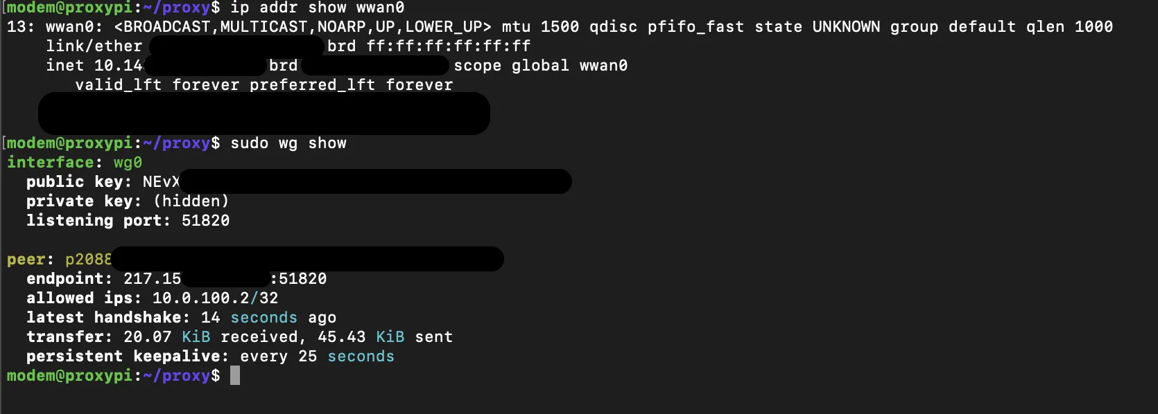
After running step 3, the WireGuard connection should be active. The quickest way to verify if this is the case, is by running sudo wg show. You want to see three things:
Latest handshake: a connection has been set up.
Transfer sent: we’re able to reach our peer.
Transfer received: the peer is able to reply.
WireGuard likes shaking hands
If this fails for some reason, it is time to start debugging! Keep the order in mind, and stop/start the services on both hosts.
sudo wg-quick down wg0
sudo wg-quick up wg0
sudo wg show
Verifying It Works
We’ve set up WireGuard on the cloud server and have connected the peer. At this point, there are three quick things you can run to verify if everything is working correctly:
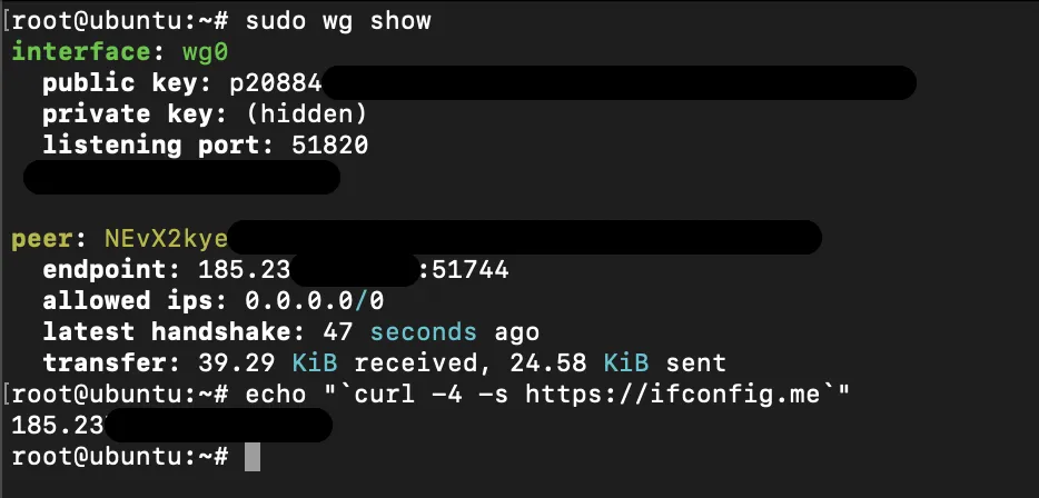
# This should display the last handshake and both packets sent as received:sudo wg show
# You should be able to ping the peer:
ping -c 4 10.0.100.1
# Your external IPv4 address should match the LTE IP
curl -4 https://ifconfig.me
So for example, sudo wg show should look something like this:
Residential cloud anyone?
Looking back at the original goal when starting this experiment, we believe it was achieved:
Or, how about this: we build our own residential proxy. No ethical considerations needed, only many evenings of tinkering and tweaking. Just the way we like it.
You may end up with a different LTE dongle and need to tweak the scripts slightly, but the underlying concept remains the same. It is entirely feasible to set up a residential proxy using relatively inexpensive hardware and use it to route cloud traffic through a mobile network. That said, you should carefully review the terms and conditions of your mobile provider, as this setup may conflict with them.
Even with those caveats, this approach is significantly more defensible from an ethical standpoint than relying on opaque residential proxy services available online.
This project turned out to be a worthwhile technical and ethical exercise, and we hope it encourages others to explore realistic adversary simulation without compromising their principles.